< Practical Electronics 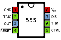
The 555 timer IC is a very versatile and useful component and can be used for many things, from giving clock pulses to switch debouncing and as an output transducer. The basic 555 IC is housed in an 8-pin carrier, and these come in DIL and SOIC formats. They run from 3-15V, and are generally quite hardy devices. The name "555" originated from a design feature, as there are three 5 kilo ohm resistors present in the input voltage divider network of the device.
Pinout
The 555 has 8 pins. The layout of these pins is shown to the right and the function of these pins in given in the table below.
| Pin | Abbrv. | Name | Function |
|---|---|---|---|
| 1 | GND | Ground Supply | This is the 0V Power Supply pin for the IC |
| 2 | TR | Trigger | A low voltage (less than 1/3 Vcc) starts the timer |
| 3 | Q | Output | This is where the output signal comes from |
| 4 | RST | Reset | A low state on this pin resets the timer, which will not be enabled until the Pin goes high again. |
| 5 | CV | Control Voltage | This is used to adject the trigger voltage. Usually, it is unused, and is connected to ground to avoid noise in the circuit. |
| 6 | THR | Threshold | This pin stops the timer when the voltage reaches 2/3 Vcc. |
| 7 | DIS | Discharge | This pin is connected to ground when the output goes low. This is used to control timing in certain applications. |
| 8 | +V | Positive Supply | The positive voltage supply to the chip. Must be between 3 and 15V. |
This article is issued from
Wikibooks.
The text is licensed under Creative
Commons - Attribution - Sharealike.
Additional terms may apply for the media files.