Abstract
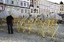
This chapter describes how to animate a complex mechanism like the strandbeest using OpenSCAD.
The model is not meant for 3D-Printing.
The source code is just one file without the use of external libraries, tested with OpenSCAD version 2015.03.
Target audience / Prerequisites
You need to have OpenSCAD installed and need to have a basic understanding in how to use OpenSCAD.
A basic understanding of geometry is necessary to understand on how to construct the linkage on paper and how to use the functions which are used to calculate the linkage. An understanding of trigonometry is helpful to understand the math behind the functions, but it is not strictly necessary.
Preparation
First of all, we need a drawing with the constants.
Theo Jansen has published the numbers on his website:
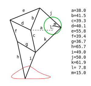
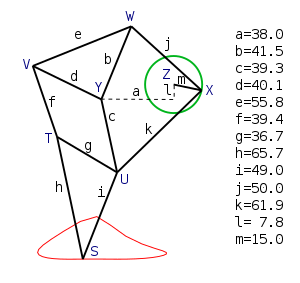
I suggest to name the points. The naming can be arbitrary. I have used Z..S to avoid confusion with the lengths a..m.
It can be very helpful to print the drawing to scribble on.
Construction by hand
Now we have to think about how we could construct the mechanism by hand.
We need a non collapsible compass, a ruler and paper.
 non collapsible compass and ruler
We set the origin Z to an arbitrary point. For Y, we are going down l and a to the left. The crank m can be at an arbitrary angle. Drawing the crank results in the point X.
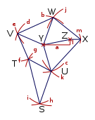
Now at this point, we construct triangles that are defined by two points and two lengths.
In geometry, this is the SSS case (constructing a Triangle with three sides given, see also Solution of triangles#Three sides given (SSS)).
On paper, this can be easily solved using a compass.
Let us start with setting the compass to length b and then putting the compass in point Y. Then we set the compass to the length j and put the compass in point X. The crossing point of the arcs is the point W.
Note that when two points and two lengths are given, there are always two solutions, speak crossing points. Given that we already know the general shape of the mechanism, we know which one we need. But keep it mind for later.
The rest is more or less "rinse and repeat".
Computer Geometry
To transfer this into source code, we need a few geometry functions.
Most of them are simple trigonometry.
Note worthy are "atan2" and the Law of cosines, implemented in the function VVLL2D (Vector Vector Length Length 2D).
All you need to know about atan2 can be read up on Wikipedia.
For the law of cosines, I recommend this article: http://www.dummies.com/education/math/trigonometry/use-the-law-of-cosines-with-sss/
Remember that with two points and two lengths, there are either two or no solutions. We can ignore the case with no solution as of now, because we know that the mechanism those not bind up. In order to get the alternate solution to the equation, the parameters can simply be swapped.
Drawing function
What we also need are some "drawing" modules. To keep it simple, the module is named rod and simply draws a rod from on point to the other.
Implementation
The implementation it self is surprisingly easy, now that we have the geometry functions to calculate the points, a module to draw a rod between two points and a general understanding on how to construct the object.
Leg Module
Let us take a look at the leg module.
The calculation is only eight lines of code and the drawing of the rods only twelve lines.
Strandbeest
For the full strandbeest we just need six legs with some spacing and angular offset.
Source
//------------------------
// Trigonometry Functions
//------------------------
function add2D(v1=[0,0],v2=[0,0]) =
[
v1[0]+v2[0],
v1[1]+v2[1]
];
function sub2D(v1=[0,0],v2=[0,0]) =
[
v1[0]-v2[0],
v1[1]-v2[1]
];
function addAngle2D(v1=[0,0],ang=0,l=0) =
[
v1[0]+cos(ang)*l,
v1[1]-sin(ang)*l
];
function getAngle2D(v1,v2=[0,0]) =
atan2(
(v2[0]-v1[0]), //dx
(v2[1]-v1[1]) //dy
);
function scale2D(v1=[0,0],c=1)=
[
v1[0]*c,
v1[1]*c,
];
function length2D(v1,v2=[0,0])=
sqrt(
(v1[0]-v2[0])*(v1[0]-v2[0])
+
(v1[1]-v2[1])*(v1[1]-v2[1])
);
//Law of cosines
function VVLL2D(v1,v2,l1,l2) =
let(sAB = length2D(v1,v2))
let(ang12=getAngle2D(v2,v1))
let(ang0=
acos(
(l2*l2-l1*l1-sAB*sAB)/
(-abs(2*sAB*l1))
))
addAngle2D(
v1=v1,
ang=ang0+ang12-90,
l=-l1
);
//----------------------
// modules (Graphic Functions)
//----------------------
// draw "rod" from v1 to v2 with thickness t
module rod(v1=[0,0],v2=[0,0],t=6){
ang1=getAngle2D(v1,v2);
len1=length2D(v1,v2);
translate([v1[0],v1[1]])
rotate([0,0,-ang1]){
translate([0,0,0]){
cylinder(r=t,h=t+2,center = true);
}
translate([-t/2,0,-t/2]){
cube([t,len1,t]);
}
}
}
//----------------------
// Leg Module // Jansen mechanism
//----------------------
module leg (
ang=0,
a=38.0, //a..m Theo Jansens Constants
b=41.5,
c=39.3,
d=40.1,
e=55.8,
f=39.4,
g=36.7,
h=65.7,
i=49.0,
j=50.0,
k=61.9,
l= 7.8,
m=15.0
)
{
Z = [0,0]; //Origin
X = addAngle2D(Z,ang,m); //Crank
Y = add2D(Z,[a,l]);
W = VVLL2D(X,Y,j,b);
V = VVLL2D(W,Y,e,d);
U = VVLL2D(Y,X,c,k);
T = VVLL2D(V,U,f,g);
S = VVLL2D(T,U,h,i); //Foot
rod(Z, X);
rod(X, W);
rod(W, Y);
rod(W, V);
rod(Y, V);
rod(X, U);
rod(Y, U);
rod(U, T);
rod(V, T);
rod(U, S);
rod(T, S);
rod(Z, Y);
//draw the foot point
translate(S){
cylinder(r=8,h=8,center = true);
}
}
//----------------------
// Strandbeest
//----------------------
module Strandbeest(ang=$t*360,o=360/3,sgap=20,mgap=50)
{
{
color([1, 0, 0]) translate([0,0,sgap*0]) leg(ang+o*0);
color([0, 1, 0]) translate([0,0,sgap*1]) leg(ang+o*1);
color([0, 0, 1]) translate([0,0,sgap*2]) leg(ang+o*2);
}
mirror(v= [1, 0, 0] ){
color([1, 0, 0]) translate([0,0,sgap*0]) leg(180-ang-o*0);
color([0, 1, 0]) translate([0,0,sgap*1]) leg(180-ang-o*1);
color([0, 0, 1]) translate([0,0,sgap*2]) leg(180-ang-o*2);
}
translate([0,0,sgap*2 + mgap])
{
color([1, 0, 0]) translate([0,0,sgap*0]) leg(180+ang+o*0);
color([0, 1, 0]) translate([0,0,sgap*1]) leg(180+ang+o*1);
color([0, 0, 1]) translate([0,0,sgap*2]) leg(180+ang+o*2);
}
translate([0,0,sgap*2 + mgap])
mirror(v= [1, 0, 0] ){
color([1, 0, 0]) translate([0,0,sgap*0]) leg(0-ang-o*0);
color([0, 1, 0]) translate([0,0,sgap*1]) leg(0-ang-o*1);
color([0, 0, 1]) translate([0,0,sgap*2]) leg(0-ang-o*2);
}
}
//leg(ang=$t*360);
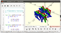
rotate([90,180,0]) Strandbeest();
Exporting the animation
OpenSCAD can export the frames of animation into PNG files. This PNG files can under Linux be turned into a gif via command line:
convert -delay 10 -loop 0 *.png myimage.gif
Convert is part of ImageMagick.
The resulting GIF can then (if necessary) be cropped with GIMP.
Next
I recommend to split the source code into different files. One way to split it is:
- Trigonometry Function
- drawing function
- Jansen Mechanism / Leg
- Strandbeest
I would recommend to use "use". This allows you to include self tests with each file.
To prettify the animation, you can draw the axes connecting the legs and/or add a support frame.
If you have access to a 3D-Printer, you can modify the code, so that the connecting points can actually rotate.