Remove the default cube

When you first open blender you will see the default Blender user interface (UI) layout and the default cube.
Delete the cube by selecting it with RMB and then pressing X .
Add a cylinder

Switch to Side view ( NUM3 ).
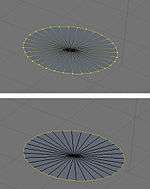
Add a Cylinder with SHIFT + A → Add→ Mesh→ Cylinder. At the bottom of the Tool Shelf change “Cap Fill Type” to “Triangle Fan”.
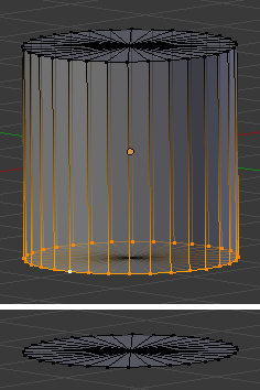
Press TAB to switch to Edit mode. The cylinder should now look like the picture at right.
Remove the bottom row of vertices
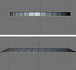
Next you will want to delete the bottom row of vertices. To accomplish this go into side view by pressing NUM3 .
Ensure that you are in Vertex select mode (that the leftmost of the group of 3 icons ![]()
Press A twice to deselect everything.
Press B , and box select the bottom row of vertices, and press X to delete and then confirm.
Note: you must have limit selection to visible off, the button to the right of the group of three icons for selection. If you wish to do the selection with it ON, you will have to change your perspective so as to be able to select all lower vertices.
Note: Instead of all of the above, you can also just add a circle with fill type 'triangle fan'
Extrude and scale to shape
Be in Vertex-select mode (as above).
Select all the vertices around the outside of the circle. The centre vertex must not be selected. You can do this conveniently in a number of ways; why not practise them all:
- Starting with no vertices selected, use A to select all vertices, then SHIFT + RMB on the centre vertex to deselect it. Or
- Starting with no vertices selected, ALT + SHIFT + RMB (loop select) on one of the outside edges or vertices to select the entire loop of them. Or
- RMB on the centre vertex to select only it, then use CTRL + I to invert the selection.
Now switch to edge-select mode by CTRL + TAB and selecting Edges.
Press E to extrude ("region") the selection and Z to constrain to the Z axis.
Drag the edges a small ways down then click LMB to release.
As this makes a right-angle at the sides and parachutes don’t have straight edges, we need to scale the selection outward.
Press S and move the mouse away from the model, you will see that the edges get smaller and bigger.
Scale them out a small ways then left click to release. You will want to practice a little with the scale amounts till you can make a realistic parachute shape.
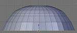
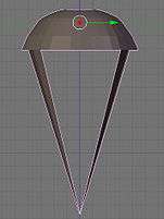
Continue extruding and scaling till you have a shape like the one shown on the right.
When you're done making a nice shape, be sure to select all ( A twice), then W and pick “Remove Doubles”.
Make the top more rounded

Be in Vertex mode.
Select the center vertex in the middle of the original top half of the cylinder, use circle select to get it, otherise you will be RMB a number of times to find it, and move G it up along the Z axis.
Select all A , and then W and Remove Doubles, in case any were created.
Extrude the parachute straps

Now go into top-view by pressing NUM7 . Here you will select ~4 edges at opposite sides of each other.

Go back into side-view NUM3 and extrude downward by pressing E and then Z .
Merge it together
All that remains to finish your parachute is to press ALT + M then choose “At Center” which will merge all selected vertices.
A alternate way to make the parachute top is to create a UV sphere, and cut it in half.