A sealed or closed box baffle is the most basic but often the cleanest sounding sub-woofer box design. The sub-woofer box in its most simple form, serves to isolate the back of the speaker from the front, much like the theoretical infinite baffle. The sealed box provides simple construction and controlled response for most sub-woofer applications. The slow low end roll-off provides a clean transition into the extreme frequency range. Unlike ported boxes, the cone excursion is reduced below the resonant frequency of the box and driver due to the added stiffness provided by the sealed box baffle.
Closed baffle boxes are typically constructed of a very rigid material such as MDF (medium density fiber board) or plywood .75 to 1 inch thick. Depending on the size of the box and material used, internal bracing may be necessary to maintain a rigid box. A rigid box is important to design in order to prevent unwanted box resonance.
As with any acoustics application, the box must be matched to the loudspeaker driver for maximum performance. The following will outline the procedure to tune the box or maximize the output of the sub-woofer box and driver combination.
Closed baffle circuit
The sealed box enclosure for sub-woofers can be modeled as a lumped element system if the dimensions of the box are significantly shorter than the shortest wavelength reproduced by the sub-woofer. Most sub-woofer applications are crossed over around 80 to 100 Hz. A 100 Hz wave in air has a wavelength of about 11 feet. Sub-woofers typically have all dimensions much shorter than this wavelength, thus the lumped element system analysis is accurate. Using this analysis, the following circuit represents a sub-woofer enclosure system.
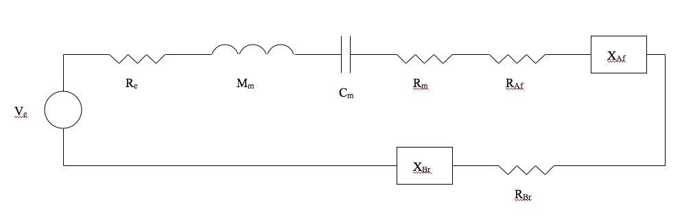
where all of the following parameters are in the mechanical mobility analog
- Ve - voltage supply
- Re - electrical resistance
- Mm - driver mass
- Cm - driver compliance
- Rm - resistance
- RAr - rear cone radiation resistance into the air
- XAf - front cone radiation reactance into the air
- RBr - rear cone radiation resistance into the box
- XBr - rear cone radiation reactance into the box
Driver parameters
In order to tune a sealed box to a driver, the driver parameters must be known. Some of the parameters are provided by the manufacturer, some are found experimentally, and some are found from general tables. For ease of calculations, all parameters will be represented in the SI units meter/kilogram/second. The parameters that must be known to determine the size of the box are as follows:
- f0 - driver free-air resonance
- CMS - mechanical compliance of the driver
- SD - effective area of the driver
Resonance of the driver
The resonance of the driver is usually either provided by the manufacturer or must be found experimentally. It is a good idea to measure the resonance frequency even if it is provided by the manufacturer to account for inconsistent manufacturing processes.
The following diagram shows verga and the setup for finding resonance:
Where voltage V1 is held constant and the variable frequency source is varied until V2 is a maximum. The frequency where V2 is a maximum is the resonance frequency for the driver.
Mechanical compliance
By definition compliance is the inverse of stiffness or what is commonly referred to as the spring constant. The compliance of a driver can be found by measuring the displacement of the cone when known masses are place on the cone when the driver is facing up. The compliance would then be the displacement of the cone in meters divided by the added weight in newtons.
Effective area of the driver
The physical diameter of the driver does not lead to the effective area of the driver. The effective diameter can be found using the following diagram:
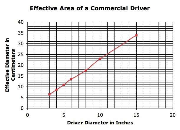
From this diameter, the area is found from the basic area of a circle equation.
Acoustic compliance
From the known mechanical compliance of the cone, the acoustic compliance can be found from the following equation:
Vas = P * C^2 * Cms * Sd^2
Where P is air density and C the speed of sound at a given temperature and pressure.
From the driver acoustic compliance, the box acoustic compliance is found. This is where the final application of the sub-woofer is considered. The acoustic compliance of the box will determine the percent shift upwards of the resonant frequency. If a large shift is desire for high SPL applications, then a large ratio of driver to box acoustic compliance would be required. If a more flattened response is desire for high fidelity applications, then a lower ratio of driver to box acoustic compliance would be required. Specifically, the ratios can be found in the following figure using line (b) as reference.
CAS = CAB*r
r - driver to box acoustic compliant ratio

Sealed box design
Volume of box
The volume of the sealed box can now be found from the box acoustic compliance. The following equation is used to calculate the box volume
VB= CAB&gam
Box dimensions
From the calculated box volume, the dimensions of the box can then be designed. There is no set formula for finding the dimensions of the box, but there are general guidelines to be followed. If the driver was mounted in the center of a square face, the waves generated by the cone would reach the edges of the box at the same time, thus when combined would create a strong diffracted wave in the listening space. In order to best prevent this, the driver should be either be mounted offset of a square face, or the face should be rectangular.
The face of the box which the driver is set in should not be a square.